Dan Freeland
03.24.2026
Summary
Constant level oilers work beautifully when the equipment behaves like a calm oil bath—but not every machine cooperates. In this article, we look at how different equipment types: horizontal pumps, vertical pumps, and gearboxes, affect oiler performance and why turbulence, pressure changes, and internal housing dynamics can create unexpected behavior. Understanding these real-world conditions helps ensure the right oiler style and installation approach keeps oil levels stable and reliable.
Where Constant Level Oilers Shine (and Where Physics Fights Back)
In our previous Lubricology article, we broke down how constant level oilers work at their core hydrostatics, the two-phase bubble/displacement cycle, and why the spout bevel sets the control point. This follow-up focuses on where that elegant physics behaves beautifully in the field… and where real-world equipment dynamics can make it a little more “interpretive.”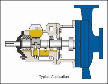 Constant level oilers are at their best when the machine behaves like a true oil bath: a relatively calm sump with a stable free surface that rises and falls predictably with oil consumption. Some equipment plays along beautifully. Others…audition for a washing machine commercial.
 Below are three common application categories, each with specific reasons a constant level oiler can be straightforward, finicky, or flat-out suboptimal. In each section we’ll highlight typical symptoms, why they happen, and practical remedies.
1) Horizontal Pumps: The Home Field Advantage (with a Few Traps)
Horizontal pump bearing housings are the classic constant-level application for a reason: geometry is usually friendly, the oil level target is well defined, and there’s often a convenient centerline port where a bullseye sight glass would live.That said, even in the “native habitat,” a few dynamics can complicate things.
Direction of rotation and oil management hardware
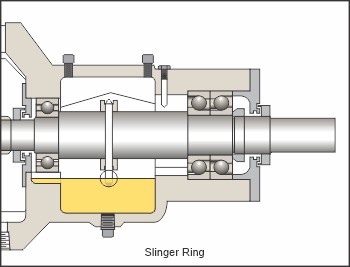 Rotation matters because it influences how the housing internally moves oil and air. Many pump housings use slinger rings or flingers designed to pick up oil and distribute it. Depending on direction of rotation and ring behavior, the housing can:
- whip oil into foam,
- entrain air,
- or create localized turbulence right where you’d prefer a calm free surface.
Watchdog and slinger rings: the “tornado effect”
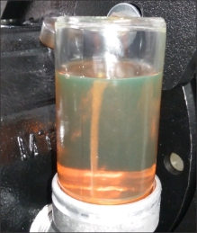
Slinger rings can create tiny bubbles as they whip through the oil and throw it onto the bearing housing walls. In many applications, a common rule of thumb is to mount the oiler in the direction of rotation but Watchdog oilers paired with slinger rings can be an exception.If a Watchdog is mounted in the direction of rotation, those tiny air bubbles can be carried toward the Watchdog spout. Because bubbles want to reach the surface, they can form a rising column through the spout and into the reservoir. This is commonly referred to as the “tornado effect.” If left unchecked, the tornado effect can continue until the oiler bottle is drained.
Why it happens: the oiler is trying to regulate a clean “level,” but the housing is temporarily behaving more like a froth generator than a calm sump.
What to do about it: several remedies can help, depending on the housing and available ports:
- Relocate the Watchdog away from the direction of rotation. It may not be the preferred arrangement, but it’s better than a self-draining oiler.
- Add baffling between the housing and the Watchdog spout. Trico offers multiple double-baffle configurations designed specifically for this scenario.
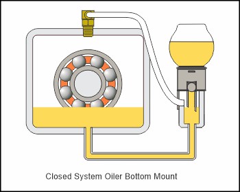
- Use a Closed System Oiler and feed from the bottom port. Because bubbles rise, placing the oil feed tube at the bottom helps prevent bubble columns from entering the feed path and eliminates the bubble-driven “tornado” behavior in many cases.
Pressure and vacuum situations (the silent saboteurs)
Standard constant level oilers assume the bearing housing behaves near atmospheric pressure or at least has stable venting. If the housing experiences:- positive pressure (case pressurization),
- vacuum or suction conditions,
- pulsing pressures driven by seals or process conditions,
- poor venting / plugged breathers,
What it looks like (pressure): with a standard vented Opto-Matic, positive pressure in the bearing housing can push down on the housing oil surface and force oil out of the Opto-Matic® at the joint between upper and lower castings often mistaken for a leak.
What it looks like (vacuum): vacuum in the bearing housing can pull oil from the vented Opto-Matic until the bottle is empty.
Why it happens: the driving forces aren’t just hydrostatic anymore, pressure differential across the system starts to dominate.
What to do about it:
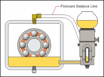
1. Replace open-system Opto-Matic units with Watchdog or a Closed System Oiler where pressure/vacuum conditions exist. Both are “closed systems,” meaning the oiler experiences (or is balanced to) the same pressure condition as the bearing housing.
- Watchdog accomplishes this inherently when installed in the centerline port.
- A Closed System Oiler accomplishes it via a pressure balancing line plumbed between the oiler headspace and the equipment headspace.
2) Vertical Pumps: Possible, but the Housing Has More Opinions
Vertical pump bearing housings can be a valid use case, but the application often introduces additional complexity that can make setup and stability more challenging. The headline issue: vertical housings are more likely to include internal geometries and rotating features that don’t behave like a calm sump.Bearing housing design and internal oil behavior
Vertical bearing housings may include features that guide oil flow, manage splash, or protect seals. Those features can unintentionally interfere with what the oiler needs most: a repeatable, measurable surface elevation.What it looks like: oil level appears different when the machine is stopped versus running, or shifts with speed/load.
Why it happens: the “level” becomes a dynamic surface, not a static reference plane.
Centrifugal forces and swirl in the housing
In vertical equipment, rotating elements can induce swirl and radial migration of oil. Centrifugal effects can move oil outward, depress the center surface, or create circumferential flow patterns. If the oiler port is exposed to turbulence, the oiler may “see” a surface that is not representative of the true bulk level. What it looks like: level appears unstable during operation; feed behavior changes with RPM.
Why it happens: the free surface is being shaped by rotation-driven flow, not just gravity.
Shrouding and “hidden” surfaces
Some vertical housings include shrouding or labyrinth features that isolate the calm surface from the port where the oiler mounts. That can make level referencing tricky: the port may not see the same surface the bearing sees. What it looks like: you set the level correctly at rest, but it behaves differently once running.
Why it happens: the oiler regulates based on the local conditions at the port, not necessarily the true internal sump behavior.
Practical bottom line: vertical pumps can work in some cases, and once set to the proper level, they may run very well but they demand a closer look at housing geometry, venting strategy, and how the oil surface behaves during operation.
3) Gearboxes: Why They’re Often Not the Best Application
Gearboxes are the frequent “sounds like a good idea” application that turns into “why is the level always moving?” The core issue is simple: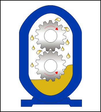
In many gearboxes, the oil level is not constant by nature.
Between gear mesh, churning, windage, and splash lubrication requirements, the sump is continuously agitated. That agitation can produce:
- surface waves and slosh,
- foam and entrained air,
- dynamic oil migration (oil carried up into the gear train and later returned),
- and a “level” that varies with speed, temperature, and load.
Why it happens: a constant level oiler regulates based on a clean surface elevation, but the gearbox is busy turning the surface into an action movie.
This is why liquid level gauges are often the best-practice solution for most gearboxes. And when gearbox reliability is the priority, dedicated filtration (and contamination control) frequently delivers more value than trying to force a “constant” level onto a constantly churning sump.
That doesn’t mean constant level oilers are never used on gear-driven equipment, but gearboxes typically require a more careful review of lubrication method (oil bath vs splash vs forced), fill volumes, venting, and where the port sits relative to turbulence zones.
Choosing the Rigth Constant Level Oiler
Even when the application gets “lively,” constant level oilers are still one of the simplest, most reliable ways to maintain an oil bath,provided the oiler style and installation match what the equipment is actually doing. Horizontal pumps are typically a natural fit, vertical pumps can be successful with the right housing awareness and level set-up, and gearboxes often benefit more from purpose-built level indication and contamination control. If you’re not sure which approach is best for your equipment or you’re seeing symptoms that don’t match the textbook, Trico can help. Reach out to our team with your equipment details (type, speed, venting, housing configuration, and target oil level), and we’ll help you select the right constant level solution and installation method to keep the oil where it belongs.Category:
Tags: