Dan Freeland
03.10.2026
Summary
Constant level oilers may look simple, but their operation is a clever application of fluid dynamics. By using hydrostatic pressure and the sealing behavior between oil and air at a precisely machined control point, the device automatically maintains a stable oil level without floats, springs, or power. This article breaks down the physics behind the system and explains how proper installation ensures reliable oil level control in oil-bath lubricated equipment.
How do these things work?
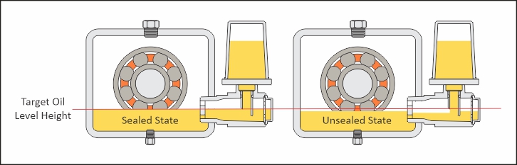
Constant level oilers look deceptively simple: a reservoir, a sight glass, and a spout. But the mechanism is a tidy piece of fluid dynamics, a passive regulator that uses hydrostatic head and a two-phase (oil and air) displacement cycle to maintain a stable oil bath. The “control element” is not a spring or float; it’s the liquid–gas interface sealing (or unsealing) the air path at a precisely defined geometry: the top inside diameter of the spout bevel. When installed correctly, the oiler feeds only when the housing level is below the setpoint and stops automatically when the level reaches the control point.
Principle of Operation
Constant level oilers were originally designed around horizontal pump bearing housings, where a consistent oil bath is essential for bearing longevity and temperature control. The same operating principle applies across many oil-bath lubricated machines any time “close enough” oil level isn’t actually close enough. At its core, a constant level oiler is a passive hydrostatic regulator. It responds to changes in oil level without external power and without moving mechanical valves. The system toggles between two stable states:
- Feed inhibited (sealed state): When the equipment oil level is at the target height, the oil surface seals the oiler’s air entry path. With no air able to enter the reservoir to replace displaced volume, oil cannot continue to leave the bottle through the spout so feeding stops.
- Feed enabled (unsealed state): When the equipment oil level drops below the target height, the seal breaks. Air is allowed into the spout, initiating a repeating cycle that delivers oil until the oil level rises back to the setpoint.
Control Point Geometry
The constant level is defined by a specific geometric feature on the spout: the top inside diameter of the spout bevel. This is the control point the exact elevation that sets the oil level in the equipment. Why does this bevel ID matter so much? Because it is the point at which the system decides whether air is allowed to enter the spout:
- Oil level at or above the bevel ID: the air pathway is blocked by the oil surface (interface seal).
- Oil level below the bevel ID: the air pathway opens (interface unsealed), allowing air intrusion.
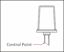 In practice, you can think of the bevel ID as an “air gate.” Oil doesn’t magically stop because it gets tired; it stops because air cannot enter to replace the volume that would have to leave the bottle. The system is volume-balanced: if air can’t enter, oil can’t keep exiting.
 This is also why the control point is so repeatable: it’s not a guess, a mark on the bottle, or a “set it where it looks right” adjustment. It is a machined geometric datum.
Two-Phase Metering Cycle
Once the equipment oil level falls below the control point, the oiler transitions into a repeatable sequence driven by hydrostatics and two-phase flow behavior. Our Watchdog viewport video captures this cycle clearly, especially with higher-viscosity oil that slows the motion.
WATCH VIDEO
Hydrostatic Driver
The pressure available to move oil is largely governed by hydrostatic head: ΔP ≈ pgΔh Where (p) is oil density, (g) is gravity, and (Δh) is the effective elevation difference that creates driving head. The important nuance: hydrostatic head can only turn into sustained delivery when air can enter to replace displaced oil volume.
Bubble Formation and Displacement (The “Piston Stroke”)
When the seal breaks at the bevel control point, air intrudes into the spout and forms a bubble at or near the bevel geometry. Bubble behavior is influenced by:
- Surface tension / Laplace pressure (resists deformation and detachment),
- Buoyancy (wants the bubble to rise),
- Viscous resistance (slows bubble growth and motion, especially noticeable at ISO 320).
In practical terms: Voil, out ≈ Vbubble
Each bubble event is a metered displacement, like a tiny piston stroke, forcing oil down and out the spout into the equipment.

Automatic Shutoff
The cycle repeats until the equipment oil level rises back to the bevel control point elevation. Once the oil surface reseals the air path:- air can no longer enter the spout,
- bubble formation stops,
- and oil delivery halts automatically at the set level.
Installation Notes
Correct installation turns a clever principle into reliable field performance. Incorrect installation turns it into…an unplanned learning opportunity.
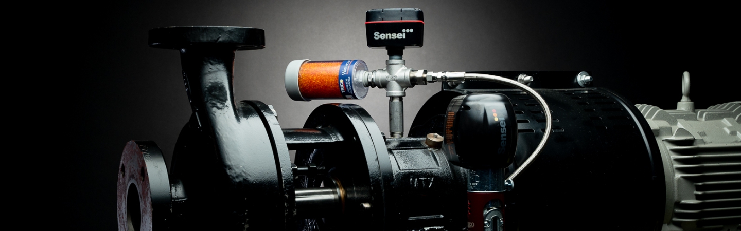
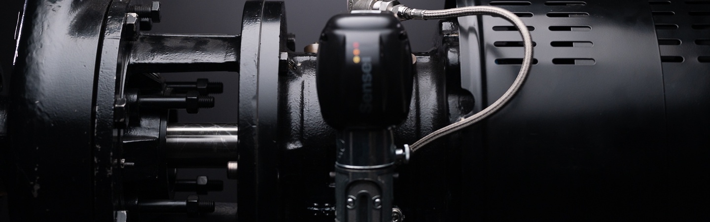
Watchdog: Centerline Mounting by Design
Watchdog oilers are designed so the spout control point aligns with the center of the viewport. This is intentional, because it makes installation unambiguous:
- Mount the Watchdog on the equipment’s oil centerline port, typically the same port used for a bullseye sight glass.
- Watchdog is a closed system and is non-adjustable because the constant level is engineered into the fixed spout geometry and its alignment with the viewport.
Opto-Matic and Closed System Opto-Matic: Below-Level Installations and Control Point Alignment
Opto-Matic oilers operate on the same bevel-defined control point principle, but they are commonly applied in an open system configuration and are often installed below the oil level. Because the oiler body is below the desired level, the design incorporates adjustability so the bevel control point can be set to match the equipment’s true centerline. Closed System Opto-Matic maintains the same bevel control mechanism while using a closed system approach, often selected when the application benefits from controlled air exchange and improved contamination management. Regardless of open or closed configuration, the core requirement remains: the bevel control point elevation must match the intended constant level.

Practical Alignment Guidance (Universal Truth)
Whether the unit is fixed-level (Watchdog) or adjustable (Opto-Matic), constant level oilers are only as accurate as their control point elevation relative to the machine’s target oil level. In other words: the spout bevel sets the oil level—so the spout bevel must be where the level should be.
System Types and Product Comparison
All Trico constant level oilers share the same foundational physics, but they differ in how the system exchanges air and how installation is achieved. All Trico constant level oilers use the same control point bevel principle; the constant level is set by the elevation of the spout’s beveled inside diameter.
Watchdog is a closed system, designed to mount at the oil centerline port, with the control point centered in the viewport and no adjustment (adjustable: no).
Opto-Matic uses the same beveled control point but is commonly applied as an open system device and is designed to be installed below the oil level, with the control point adjustable (adjustable: yes) so the bevel elevation can be aligned to the equipment’s true centerline.
Closed System Opto-Matic retains the same bevel-defined control point while providing a closed system approach, selected when the application benefits from controlled air exchange/contamination management, and it likewise depends on setting the control point correctly during installation.
Application Considerations
Constant level oilers are broadly effective in oil-bath lubrication, but it helps to remember what they are (and are not):
- They are level regulators, not pumps.
- They respond to level change through interface sealing, not through mechanical valves.
- They are most predictable when the equipment behaves like a stable oil bath and when the installation supports a clean control point reference.
- Oil can not go back up into the bottle, it is a one way valve.
Challenges by Application (Coming Next on Lubricology)
Not every oil bath application behaves like a textbook pump bearing housing. Venting strategy, pressure pulsations, thermal expansion, internal turbulence, return paths, and mounting constraints can all influence performance, oil stability, and installation best practices. In the next Lubricology article, we’ll break down the most common application-specific challenges by equipment type what causes them, how to spot them, and how to select the right configuration (open vs closed, fixed vs adjustable) to keep the oil level steady and the troubleshooting conversations short. Category:
Tags: